Arduino Matrix szenzor

Processing/Wiring (illetve C) nyelvű programozási fogások, tippek. (AVR-Duino, Arduino, EthDuino, Diecimila, Severino, Nano, LilyPad)
Válasz küldése
bbking
Újonc
Újonc
Hozzászólások: 10
Csatlakozott: 2014. március 4. kedd, 11:01

Arduino Matrix szenzor

Hozzászólás Szerző: bbking »

Sziasztok

Segítséget szeretnék kérni matrix érzékelő beolvasással kapcsolatban.
Ezt a progit használom de nem a legjobb, ha bárkinek lenne 5 lete hogyan lehetne beolvasni nyomás érzékelésre használnám.
Csatolom az érzékelő linkjét is.
http://sensitronics.com/img/4_x_3_25_Th ... sample.png
////////Arduino mega 8x8 matrix kód//////////

Kód: Egész kijelölése

int Pin0 = A0;        // sensor attached to analog Pin0
int Pin1 = A1;        // sensor attached to analog Pin1
int Pin2 = A2;        // sensor attached to analog Pin2
int Pin3 = A3;        // sensor attached to analog Pin3
int Pin4 = A4;        // sensor attached to analog Pin4
int Pin5 = A5;        // sensor attached to analog Pin5
int Pin6 = A6;        // sensor attached to analog Pin5
int Pin7 = A7;        // sensor attached to analog Pin5


int dPin[] = {2, 3, 4, 5, 6, 7, 8, 9}; //declaration of the pins we will use; i is the position within the array; i = 0 corresponds to output 2
int i = 0;

int sensorValue0 = 0; //value read from line 0 of the sensor
int sensorValue1 = 1; //value read from line 1 of the sensor
int sensorValue2 = 2; //value read from line 2 of the sensor
int sensorValue3 = 3; //value read from line 3 of the sensor
int sensorValue4 = 4; //value read from line 4 of the sensor
int sensorValue5 = 5; //value read from line 5 of the sensor
int sensorValue6 = 6; //value read from line 5 of the sensor
int sensorValue7 = 7; //value read from line 5 of the sensor

int msensorValue0 = 0; // mapped value read from line 0 of the sensor
int msensorValue1 = 1; // mapped value read from line 1 of the sensor
int msensorValue2 = 2; // mapped value read from line 2 of the sensor
int msensorValue3 = 3; // mapped value read from line 3 of the sensor
int msensorValue4 = 4; // mapped value read from line 4 of the sensor
int msensorValue5 = 5; // mapped value read from line 5 of the sensor
int msensorValue6 = 6; // mapped value read from line 5 of the sensor
int msensorValue7 = 7; // mapped value read from line 5 of the sensor

void setup() {
  
  for (int i = 7; i >= 0 ; i--) {
pinMode(dPin[i], OUTPUT);             //declaration of pin[i] as an OUTPUT

pinMode (Pin0, INPUT);
pinMode (Pin1, INPUT);
pinMode (Pin2, INPUT);
pinMode (Pin3, INPUT);
pinMode (Pin4, INPUT);
pinMode (Pin5, INPUT);
pinMode (Pin6, INPUT);
pinMode (Pin7, INPUT);

}
  Serial.begin(9600);   //turn serial on
}

void loop(){
  
 for (int i = 7; i >= 0 ; i--) { 
                                  
  digitalWrite (dPin[i], HIGH); //turn row i on 
  sensorValue0 = analogRead (Pin7); //read value column 0
  // wait 10 milliseconds before the next loop
  // for the analog-to-digital converter to settle
  // after the last reading:
  delay(10);   
  sensorValue1 = analogRead (Pin6); //read value column 1
  delay(10);
  sensorValue2 = analogRead (Pin5); //read value column 2
  delay(10);
  sensorValue3 = analogRead (Pin4); //read value column 3
  delay(10);
  sensorValue4 = analogRead (Pin3); //read value column 4
  delay(10);
  sensorValue5 = analogRead (Pin2); //read value column 5
  delay(10);
  sensorValue6 = analogRead (Pin1); //read value column 5
  delay(10);
  sensorValue7 = analogRead (Pin0); //read value column 5
  delay(10);
  digitalWrite (dPin[i], LOW); //turn row i off 
  
   
  msensorValue0 = map (sensorValue0, 0, 1023, 255, 0);    //map all values read to a new range from 255 to 0
  msensorValue1 = map (sensorValue1, 0, 1023, 255, 0);
  msensorValue2 = map (sensorValue2, 0, 1023, 255, 0);
  msensorValue3 = map (sensorValue3, 0, 1023, 255, 0);
  msensorValue4 = map (sensorValue4, 0, 1023, 255, 0);
  msensorValue5 = map (sensorValue5, 0, 1023, 255, 0);
  msensorValue6 = map (sensorValue6, 0, 1023, 255, 0);
  msensorValue7 = map (sensorValue7, 0, 1023, 255, 0);
  
  Serial.print(msensorValue0);   //print first value on the serial port
  Serial.print(',');             // print comma
  Serial.print(msensorValue1);   //print second value on the serial port
  Serial.print(',');            //.....
  Serial.print(msensorValue2);
  Serial.print(',');
  Serial.print(msensorValue3);
  Serial.print(',');
  Serial.print(msensorValue4);
  Serial.print(',');
  Serial.print(msensorValue5);
  Serial.print(',');
  Serial.print(msensorValue6);
Serial.print(',');
  Serial.print(msensorValue7);
  if (i > 0){                   //don't print the comma at the end for the first 7 packages of data
  Serial.print(','); 
}
}
Serial.println ();   //print a blank line - this line is important because Processing will start a serial event only after reading this blank line. 
}
bbking
Újonc
Újonc
Hozzászólások: 10
Csatlakozott: 2014. március 4. kedd, 11:01

Re: Arduino Matrix szenzor

Hozzászólás Szerző: bbking »

Sziasztok


Találtam egy másik megoldást csak sajnos hiányosak az információk.
Ha valaki tudna segíteni egy kapcsolási rajzot készíteni akkor lehet hogy működőképes lenne a dolog illetve ha tudnánk hogy mi hiányzik még a kapcsolásból.
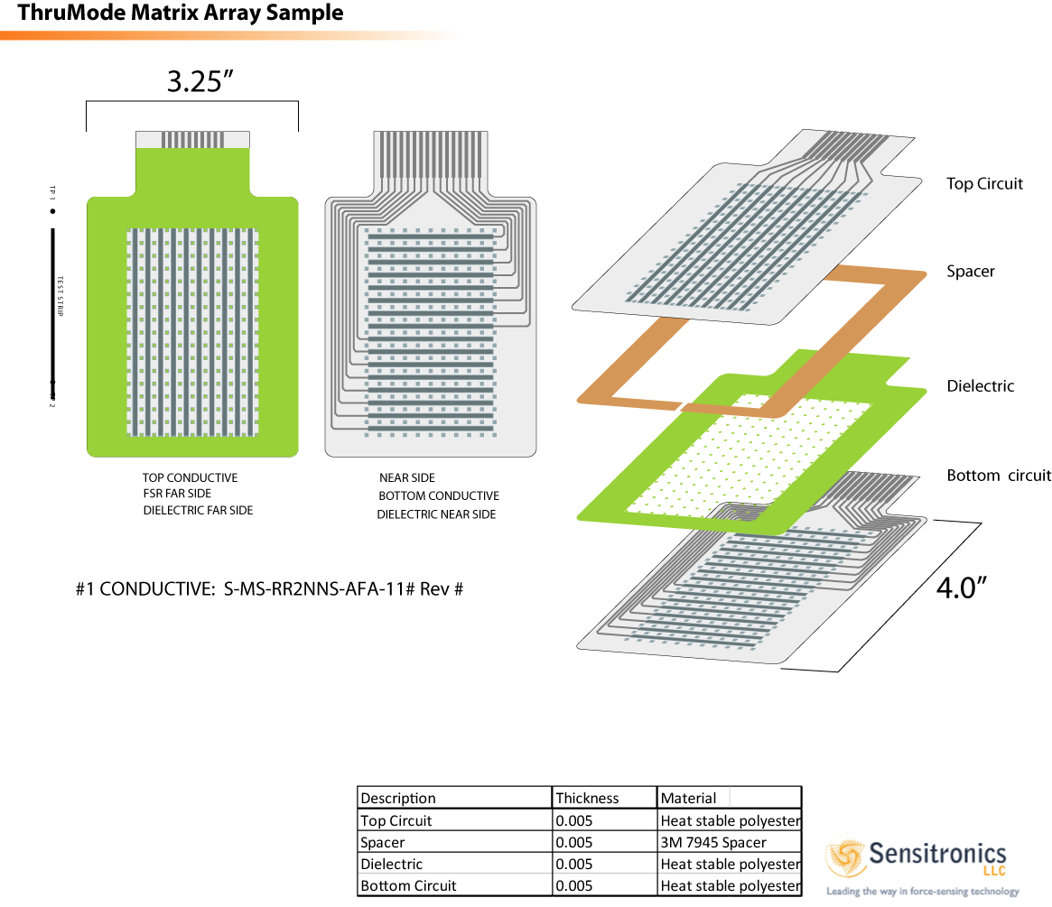
Csatolom a két linket az egyiken látható pár haszon infó "sajnos a cég már nem elérhető"

https://sites.google.com/a/sensibleui.c ... user_guide

És a Ardunio kódot amit használtak

Kód: Egész kijelölése

#include <Stdio.h>


//-----------------------------------------------------------------------------

// ArduMT MACROs and control parameters

//-----------------------------------------------------------------------------

#define FASTSCAN 1 // Do fast scanning

#define FASTADC  1 // Do fast ADC

#define TIME_CHK 0 // For debugging


// ADC channel

#define ADC_CHANNEL 0


// ADC value

#define MEASUREMENT_DIVIDE 2 // measurement = adc / MEASUREMENT_DIVIDE


// ADC value less than the threshold value is

// regarded as zero

const int encodingThreshold = 20;


// 0:   No Test. Run ArduMT firmware

// 1~5: For debugging. See function testArduMT()

#define TEST_ARDUMT 1


// Reserved for future use

#define MIN_ADC 0

#define MAX_ADC 1023


// RS232C BAUD_RATE

#define BAUD_RATE 115200


// Fast ADC code from

// http://www.arduino.cc/cgi-bin/yabb2/YaBB.pl?num=1208715493/11

// defines for setting and clearing register bits

#ifndef cbi

#define cbi(sfr, bit) (_SFR_BYTE(sfr) &= ~_BV(bit))

#endif

#ifndef sbi

#define sbi(sfr, bit) (_SFR_BYTE(sfr) |= _BV(bit))

#endif


//=============================================================================

// Variables and constants Változók és állandók

//=============================================================================


// Number of driving and sensinig electrodes. Számú vezetési és érzékelő elektródákat.

// Although the current ArduMT panel has 30 sensing electrodes Bár a jelenlegi ArduMT panel 30 érzékelő elektródák

// its sensing electronics supports 40 channels. az érzékelő elektronika támogatja a 40 csatorna.

const int nDriving = 40;

const int nSensing = 30;

const int nDrivingModuleChannel = 40;

const int nSensingModuleChannel = 40;


// Shift register control settings. Shift regiszter beállításokat.

// ArduMT uses shift registers to address a single touch pixel. ArduMT használ váltás nyilvántartások, amelyek foglalkoznak egy képpont felbontású érintőképernyő.

// This addressing method can reduce the required number of Arduino digital Ez a címzési módszer csökkentheti a szükséges számú Arduino digitális

// output pins, especially when there are large number of electrodes. kimeneti csapok, különösen akkor, ha nagy számú elektródák.


// Settings for ArduMT

// Pin connected to latch pin (ST_CP) of 74HC595

const int latchPinD = 8;

const int latchPinS = 11;

// Pin connected to clock pin (SH_CP) of 74HC595

const int clockPinD = 9;

const int clockPinS= 10;

// Pin connected to Data in (DS) of 74HC595

const int dataPinD = 7;

const int dataPinS = 12;


const int latchPinSPORTB = B00001000; // Digital Pin 11

const int clockPinSPORTB = B00000100; // Digital Pin 10

const int dataPinSPORTB = B00010000; // Digital Pin 12


int incomingByte = 0;


// Encoding control parameters

const int MAX_NUM_ENCODED_ZEROS = 254;

const int MAX_MEASUREMENT = 254;

const int END_PACKET = 255;


// Time check variables and functions for debuggin ArduMT Idő ellenőrzés változók és funkciók debuggin ArduMT

#if TIME_CHK

unsigned long begin_time;

unsigned long end_time;

unsigned long elapsed_time;

#endif


//=============================================================================

// Function bodies Funkció szervek

//=============================================================================


#if TIME_CHK

void time_chk_start(void)

{

    begin_time = micros();

}


void time_chk_stop(void)

{

    end_time = micros();


    elapsed_time = end_time - begin_time;


    Serial.print("Time (micro s): ");

    Serial.println(elapsed_time);

}

#endif


/** Real-time encoding (compression) of ADC measurement */

void encodeData(int measurement, int &count)

{

    if( measurement < encodingThreshold )  // consider as 0

    {

        if(count < (MAX_NUM_ENCODED_ZEROS-1))

        {

            count++;

        }

        else

        {

#if !TIME_CHK

            Serial.print(0, BYTE);

            //Serial.print(255, BYTE);

            Serial.print(MAX_NUM_ENCODED_ZEROS, BYTE);

#endif

            count = 0;

        }

    }

    else

    {

        if( count != 0 )

        {

#if !TIME_CHK

            Serial.print(0, BYTE);

            Serial.print(count, BYTE);

#endif

            count = 0;

        }

#if !TIME_CHK


      if(MAX_MEASUREMENT < (measurement/MEASUREMENT_DIVIDE))

      {

         Serial.print(MAX_MEASUREMENT, BYTE);

      }

      else

      {

         Serial.print(measurement/MEASUREMENT_DIVIDE, BYTE);

      }

#endif

    }

}


/** For testting ArduMT, only for development purpose */

void testArduMT(int testNumber)

{

    initializeShiftRegisters(dataPinD, clockPinD, latchPinD, nDriving);

    initializeShiftRegisters(dataPinS, clockPinS, latchPinS, nSensing);


    byte command1 = 'S'; // 83, Uncompressed data transfer. Packet length is nDriving*nSensing bytes

    int measurement = 0;


    switch (testNumber)

    {

    case 1: // sensing point (0, 0)

        shiftOutBit(dataPinD, clockPinD, latchPinD, 1);

        shiftOutBitHighSpeedPORTB(dataPinSPORTB, clockPinSPORTB, latchPinSPORTB, 1);

        while (1) {}

        break;

    case 2: // sensing point (29, 0)

        for (int j = 0 ; j < 29; j++)

        {

            if (j == 0)

            {

                initializeShiftRegisters(dataPinS, clockPinS, latchPinS, nSensing);

                shiftOutBitHighSpeedPORTB(dataPinSPORTB, clockPinSPORTB, latchPinSPORTB, 1);

            }

            else

            {

                shiftOutBitHighSpeedPORTB(dataPinSPORTB, clockPinSPORTB, latchPinSPORTB, 0);

            }

        }

        while (1) {}

        break;

    case 3: // sensing point (30, 0)

        for (int j = 0; j < 30; j++)

        {

            if (j == 0)

            {

                initializeShiftRegisters(dataPinS, clockPinS, latchPinS, nSensing);

                shiftOutBitHighSpeedPORTB(dataPinSPORTB, clockPinSPORTB, latchPinSPORTB, 1);

            }

            else

            {

                shiftOutBitHighSpeedPORTB(dataPinSPORTB, clockPinSPORTB, latchPinSPORTB, 0);

            }

        }

        while (1) {};

        break;

    case 4: // low-speed scanning with initialization (zero out sensor shift registers)

        while(1)

        {

            if (Serial.available() > 0)

            {

                incomingByte = Serial.read();

                if (incomingByte == command1)

                {

                    for (int j = 0 ; j < nDriving; j++)

                    {

                        if (j == 0)

                        {

                            initializeShiftRegisters(dataPinS, clockPinS, latchPinS, nSensing);

                            shiftOutBit(dataPinS, clockPinS, latchPinS, 1);

                        }

                        else

                        {

                            shiftOutBit(dataPinS, clockPinS, latchPinS, 0);

                        }


                        measurement = analogRead(ADC_CHANNEL);

                        Serial.print(measurement/MEASUREMENT_DIVIDE, BYTE);

                    }

                }

            }

        }

        break;

    case 5: // high-speed scanning with initialization (zero out sensor shift registers)

        while(1)

        {

            if (Serial.available() > 0)

            {

                incomingByte = Serial.read();

                if (incomingByte == command1)

                {

                    for (int j = 0 ; j < nDriving; j++)

                    {

                        if (j == 0)

                        {

                            initializeShiftRegisters(dataPinS, clockPinS, latchPinS, nSensing);

                            shiftOutBitHighSpeedPORTB(dataPinSPORTB, clockPinSPORTB, latchPinSPORTB, 1);

                        }

                        else

                        {

                            shiftOutBitHighSpeedPORTB(dataPinSPORTB, clockPinSPORTB, latchPinSPORTB, 0);

                        }


                        measurement = analogRead(ADC_CHANNEL);

                        Serial.print(measurement/MEASUREMENT_DIVIDE, BYTE);

                    }

                }

            }

        }

        break;

    default:

        break;

    }

}


void setup()

{

#if FASTADC

    // set prescale to 16

    sbi(ADCSRA,ADPS2) ;

    cbi(ADCSRA,ADPS1) ;

    cbi(ADCSRA,ADPS0) ;

#endif


    // Initialize scanning electronics

    pinMode(latchPinD, OUTPUT);

    pinMode(latchPinS, OUTPUT);

    pinMode(dataPinD, OUTPUT);

    pinMode(dataPinS, OUTPUT);

    pinMode(clockPinD, OUTPUT);

    pinMode(clockPinS, OUTPUT);


    initializeShiftRegisters(dataPinD, clockPinD, latchPinD, nDriving);

    initializeShiftRegisters(dataPinS, clockPinS, latchPinS, nSensing);


    // Initialize serial port

    Serial.begin(BAUD_RATE);


#if TEST_ARDUMT

        testArduMT(TEST_ARDUMT);

#endif

}


void loop()

{

    int measurement = 0;

    int count = 0;


    byte command1 = 'S'; // 83, Uncompressed data transfer. Packet length is nDriving*nSensing bytes

    byte command2 = 'F'; // 70, Compressed data transfer. Variable packet length.

    byte command_ain = 'A'; // Analog in.


    //byte command_ain = 'A'; // Analog in

    //byte command_a1 = 'A1'; // Analog in


    if (Serial.available() > 0)

    {

        incomingByte = Serial.read();

        if (incomingByte == command1)

        {

#if TIME_CHK

            time_chk_start();

#endif

            for (int i = 0; i < nDriving; i++)

            {

                /*

                 if (i == 0) shiftOutBitHighSpeedPORTB(dataPinSPORTB, clockPinSPORTB, latchPinSPORTB, 1);

                 else shiftOutBitHighSpeedPORTB(dataPinSPORTB, clockPinSPORTB, latchPinSPORTB, 0);

                 */

                if (i == 0) shiftOutBit(dataPinD, clockPinD, latchPinD, 1);

                else shiftOutBit(dataPinD, clockPinD, latchPinD, 0);


                for (int j = 0 ; j < nSensingModuleChannel; j++)

                {

#if FASTSCAN

                    if (j == 0)

                    {

                        shiftOutBitHighSpeedPORTB(dataPinSPORTB, clockPinSPORTB, latchPinSPORTB, 1);

                    }

                    else

                    {

                        shiftOutBitHighSpeedPORTB(dataPinSPORTB, clockPinSPORTB, latchPinSPORTB, 0);

                    }

#else

                    // Driving, sensing electrode control using 595

                    if (j == 0)

                    {

                        shiftOutBit(dataPinS, clockPinS, latchPinS, 1);

                    }

                    else

                    {

                        shiftOutBit(dataPinS, clockPinS, latchPinS, 0);

                    }

#endif


                    if (j < nSensing)

                    {

                        measurement = analogRead(ADC_CHANNEL);

#if !TIME_CHK

                        if(MAX_MEASUREMENT < (measurement/MEASUREMENT_DIVIDE))

                        {

                            Serial.print(MAX_MEASUREMENT, BYTE);

                        }

                        else

                        {

                            Serial.print(measurement/MEASUREMENT_DIVIDE, BYTE);

                        }

#endif

                    }

                }

            }

#if TIME_CHK

            time_chk_stop();

#endif

        }

        else if (incomingByte == command2)

        {

#if TIME_CHK

            time_chk_start();

#endif

            for (int i = 0; i < nDriving; i++)

            {

                if (i == 0) shiftOutBit(dataPinD, clockPinD, latchPinD, 1);

                else shiftOutBit(dataPinD, clockPinD, latchPinD, 0);


                for (int j = 0 ; j < nSensingModuleChannel; j++)

                {

#if FASTSCAN

                    if (j == 0)

                    {

                        shiftOutBitHighSpeedPORTB(dataPinSPORTB, clockPinSPORTB, latchPinSPORTB, 1);

                    }

                    else

                    {

                        shiftOutBitHighSpeedPORTB(dataPinSPORTB, clockPinSPORTB, latchPinSPORTB, 0);

                    }

#else

                    // Driving, sensing electrode control using 595

                    if (j == 0)

                    {

                        shiftOutBit(dataPinS, clockPinS, latchPinS, 1);

                    }

                    else

                    {

                        shiftOutBit(dataPinS, clockPinS, latchPinS, 0);

                    }

#endif


                    if (j < nSensing)

                    {

                        measurement = analogRead(ADC_CHANNEL);

                        encodeData(measurement, count);

                    }

                }

            }


            // End of encoded packet

            if( count != 0)

            {

#if !TIME_CHK

                Serial.print(0, BYTE);

                Serial.print(count, BYTE);

#endif

                count = 0;

            }


#if !TIME_CHK

            Serial.print(END_PACKET, BYTE);

            Serial.print(END_PACKET, BYTE);

#endif


#if TIME_CHK

            time_chk_stop();

#endif

        }


        else if (incomingByte == command_ain)

        {

            //int aport = Serial.read();

            //measurement = analogRead(aport);

            measurement = analogRead(1);

            Serial.print(measurement, BYTE);

            measurement = analogRead(2);

            Serial.print(measurement, BYTE);

            measurement = analogRead(3);

            Serial.print(measurement, BYTE);

            measurement = analogRead(4);

            Serial.print(measurement, BYTE);

            measurement = analogRead(5);

            Serial.print(measurement, BYTE);

        }

        /*

        else if (incomingByte == command_a2)

        {

            measurement = analogRead(2);

            Serial.print(measurement, BYTE);

        }

        */

    }

}


void shiftOutBit(int myDataPin, int myClockPin, int myLatchPin, int myDataOut)

{

    // This shifts 8 bits out MSB first, on the rising edge of the clock,

    // clock idles low


    // internal function setup

    int i=0;

    int pinState;


    digitalWrite(myLatchPin, 0);


    // clear everything out just in case to

    // prepare shift register for bit shifting

    digitalWrite(myDataPin, 0);

    digitalWrite(myClockPin, 0);


    // if the value passed to myDataOut and a bitmask result

    // true then... so if we are at i=6 and our value is

    // %11010100 it would the code compares it to %01000000

    // and proceeds to set pinState to 1.

    if ( myDataOut )

    {

        pinState= 1;

    }

    else

    {

        pinState= 0;

    }


    //Sets the pin to HIGH or LOW depending on pinState

    digitalWrite(myDataPin, pinState);

    //register shifts bits on upstroke of clock pin

    digitalWrite(myClockPin, 1);

    //zero the data pin after shift to prevent bleed through

    digitalWrite(myDataPin, 0);


    //stop shifting

    digitalWrite(myClockPin, 0);

    digitalWrite(myLatchPin, 1);

}


// Highspeed version of shiftOutBit() function for PORTB pins (digital pin 8 ~ 13)

// Therefore, this function can replace shiftOutBit() for sensing electrodes.

// References:

// http://www.arduino.cc/en/Reference/PortManipulation

// http://www.arduino.cc/cgi-bin/yabb2/YaBB.pl?num=1230286016

void shiftOutBitHighSpeedPORTB(int myDataPin, int myClockPin, int myLatchPin, int myDataOut)

{

    PORTB &= ~(myLatchPin | myDataPin | myClockPin);


    // Sets the ddata pin to HIGH or LOW depending on myDataOut

    if ( myDataOut )

    {

        PORTB |= myDataPin;

    }

    else

    {

        PORTB &= ~myDataPin;

    }


    // register shifts bits on upstroke of clock pin

    PORTB |= myClockPin;


    // zero the data pin after shift to prevent bleed through

    PORTB &= ~myDataPin;


    // stop shifting

    PORTB &= ~myClockPin;


    PORTB |= myLatchPin;

}


void initializeShiftRegisters(int whichRegister, int clockPin, int latchPin, int numRegisters)

{

    digitalWrite(latchPin, LOW);


    for (int i = 0; i < numRegisters; i++)

    {


        shiftOut(whichRegister, clockPin, MSBFIRST, 0);


    }


    digitalWrite(latchPin, HIGH);

}


bbking
Újonc
Újonc
Hozzászólások: 10
Csatlakozott: 2014. március 4. kedd, 11:01

Re: Arduino Matrix szenzor

Hozzászólás Szerző: bbking »

Sziasztok

Csatolok be egy rajzot a kérdésem az lenne hogy TLC082 illetve LTC1983-5 ezeket tudnám valamivel helyetesíteni?

https://drive.google.com/file/d/0B7hqSP ... sp=sharing

Üdv

Balázs
Avatar
kapu48
Elektronbűvölő
Hozzászólások: 3375
Csatlakozott: 2008. augusztus 29. péntek, 6:00

Re: Arduino Matrix szenzor

Hozzászólás Szerző: kapu48 »

Segít a Google!

Csak keresni kellene!

Pl.: http://www.alldatasheet.com/datasheet-p ... C0820.html?
bbking
Újonc
Újonc
Hozzászólások: 10
Csatlakozott: 2014. március 4. kedd, 11:01

Re: Arduino Matrix szenzor

Hozzászólás Szerző: bbking »

Sziasztok

Egy kis segítséget szeretnék kétni az olvasási sebességet szeretném emelni a jelenlegi ~258Hz ről 500Hz-re
A kapcsolásba 2db 74HC595 Shift Register 2db 74HC4051 Analog Multiplexer van
Arduino mega 2560

Kód: Egész kijelölése

/**********************************************************************************************************
 * MACROS / PIN DEFS
 **********************************************************************************************************/
 #define BAUD_RATE                 115200
 #define ROW_COUNT                 10
 #define COLUMN_COUNT              16
 
#define PIN_ADC_INPUT             A0
 #define PIN_SHIFT_REGISTER_DATA   2
 #define PIN_SHIFT_REGISTER_CLOCK  3
 #define PIN_MUX_CHANNEL_0         4  //channel pins 0, 1, 2, etc must be wired to consecutive Arduino pins
 #define PIN_MUX_CHANNEL_1         5
 #define PIN_MUX_CHANNEL_2         6
 #define PIN_MUX_INHIBIT_0         7  //inhibit = active low enable. All mux IC enables must be wired to consecutive Arduino pins
 #define PIN_MUX_INHIBIT_1         8
 
#define SET_SR_DATA_HIGH()        PORTD|=B00000100
 #define SET_SR_DATA_LOW()         PORTD&=~B00000100
 #define SET_SR_CLK_HIGH()         PORTD|=B00001000
 #define SET_SR_CLK_LOW()          PORTD&=~B00001000
 
#define ROWS_PER_MUX              8
 #define MUX_COUNT                 2
 #define CHANNEL_PINS_PER_MUX      3
 
#define PACKET_END_BYTE           0xFF
 #define MAX_SEND_VALUE            254  //reserve 255 (0xFF) to mark end of packet
 #define COMPRESSED_ZERO_LIMIT     254
 #define MIN_SEND_VALUE            1    //values below this threshold will be treated and sent as zeros
 
#ifndef cbi
 #define cbi(sfr, bit) (_SFR_BYTE(sfr) &= ~_BV(bit))
 #endif
 #ifndef sbi
 #define sbi(sfr, bit) (_SFR_BYTE(sfr) |= _BV(bit))
 #endif
 
/**********************************************************************************************************
 * GLOBALS
 **********************************************************************************************************/
 int current_enabled_mux = MUX_COUNT - 1;  //init to number of last mux so enabled mux increments to first mux on first scan.
 int compressed_zero_count = 0;
 

/**********************************************************************************************************
 * setup()
 **********************************************************************************************************/
 void setup()
 {
   Serial.begin(BAUD_RATE);
   pinMode(PIN_ADC_INPUT, INPUT);
   pinMode(PIN_SHIFT_REGISTER_DATA, OUTPUT);
   pinMode(PIN_SHIFT_REGISTER_CLOCK, OUTPUT);
   pinMode(PIN_MUX_CHANNEL_0, OUTPUT);
   pinMode(PIN_MUX_CHANNEL_1, OUTPUT);
   pinMode(PIN_MUX_CHANNEL_2, OUTPUT);
   pinMode(PIN_MUX_INHIBIT_0, OUTPUT);
   pinMode(PIN_MUX_INHIBIT_1, OUTPUT);
   
   sbi(ADCSRA,ADPS2);  //set ADC prescaler to CLK/16
   cbi(ADCSRA,ADPS1);
   cbi(ADCSRA,ADPS0);
 }
 

/**********************************************************************************************************
 * loop()
 **********************************************************************************************************/
 void loop()
 {
   compressed_zero_count = 0;
   for(int i = 0; i < ROW_COUNT; i ++)
   {
     setRow(i);
     shiftColumn(true);
     for(int j = 0; j < COLUMN_COUNT; j ++)
     {
       int raw_reading = analogRead(PIN_ADC_INPUT);
       byte send_reading = (byte) (lowByte(raw_reading >> 2));
       shiftColumn(false);
       sendCompressed(send_reading);
     }
   }
   if(compressed_zero_count > 0)
   {
     Serial.write((byte) 0);
     Serial.write((byte) compressed_zero_count);
   }
   Serial.write((byte) PACKET_END_BYTE);
 }
 

/**********************************************************************************************************
 * setRow() - Enable single mux IC and channel to read specified matrix row. digitalWrite() have not been
 * replaced in this function, as mux changes are relatively infrequent.
 **********************************************************************************************************/
 void setRow(int row_number)
 {
   if((row_number % ROWS_PER_MUX) == 0)  //We've reached channel 0 of a mux IC, so disable the previous mux IC, and enable the next mux IC
   {
     digitalWrite(PIN_MUX_INHIBIT_0 + current_enabled_mux, HIGH);  //This offset is why mux inhibits must be wired to consecutive Arduino pins
     current_enabled_mux ++;
     if(current_enabled_mux >= MUX_COUNT)
     {
       current_enabled_mux = 0;
     }
     digitalWrite(PIN_MUX_INHIBIT_0 + current_enabled_mux, LOW);  //enable the next mux, active low
   }
   for(int i = 0; i < CHANNEL_PINS_PER_MUX; i ++)
   {
     if(bitRead(row_number, i))
     {
       digitalWrite(PIN_MUX_CHANNEL_0 + i, HIGH);
     }
     else
     {
       digitalWrite(PIN_MUX_CHANNEL_0 + i, LOW);
     }
   }
 }
 

/**********************************************************************************************************
 * shiftColumn() - Shift out a high bit to drive first column, or increment column by shifting out a low
 * bit to roll high bit through cascaded shift register outputs. digitalWrite() has been replaced with direct
 * port manipulation macros, as this function performs the vast majority of pin writes
 **********************************************************************************************************/
 void shiftColumn(boolean is_first)
 {
   if(is_first)
   {
     SET_SR_DATA_HIGH();
   }
   SET_SR_CLK_HIGH();
   SET_SR_CLK_LOW();
   if(is_first)
   {
     SET_SR_DATA_LOW();
   }
 }
 

/**********************************************************************************************************
 * sendCompressed() - If value is nonzero, send it via serial terminal as a single byte. If value is zero,
 * increment zero count. The current zero count is sent and cleared before the next nonzero value
 **********************************************************************************************************/
 void sendCompressed(byte value)
 {
   if(value < MIN_SEND_VALUE)
   {
     if(compressed_zero_count < (COMPRESSED_ZERO_LIMIT - 1))
     {
       compressed_zero_count ++;
     }
     else
     {
       Serial.write((byte) 0);
       Serial.write((byte) COMPRESSED_ZERO_LIMIT);
       compressed_zero_count = 0; 
     }
   }
   else
   {
     if(compressed_zero_count > 0)
     {
       Serial.write((byte) 0);
       Serial.write((byte) compressed_zero_count);
       compressed_zero_count = 0;
     }
     if(value > MAX_SEND_VALUE)
     {
        Serial.write((byte) MAX_SEND_VALUE);
     }
     else
     {
        Serial.write((byte) value);
     }
   }
 }
 
Avatar
kapu48
Elektronbűvölő
Hozzászólások: 3375
Csatlakozott: 2008. augusztus 29. péntek, 6:00

Re: Arduino Matrix szenzor

Hozzászólás Szerző: kapu48 »

Meg nézed a proci adatlapját, hogy lehet e az ADC prescela-t 8-ra állítani?
És a setup részben javitod a megfelelö értékeket.

Itt valami hiányzik:
byte send_reading = (byte ???) ; <<<<<<<
bbking
Újonc
Újonc
Hozzászólások: 10
Csatlakozott: 2014. március 4. kedd, 11:01

Re: Arduino Matrix szenzor

Hozzászólás Szerző: bbking »

Szia

Köszönöm a gyors választ sajnos nem vagyok jártas ez ügyben.
Ha tudnál egy kis útmutatás írni azt nagyon megköszönném.
Kerestem a neten de konkrét példát nem találtam

Table 10-15. Clock Prescaler Select
CLKPS3 CLKPS2 CLKPS1 CLKPS0 Clock Division Factor
0 0 0 0 1
0 0 0 1 2
0 0 1 0 4
0 0 1 1 8
0 1 0 0 16
0 1 0 1 32
0 1 1 0 64
0 1 1 1 128
1 0 0 0 256
Avatar
kapu48
Elektronbűvölő
Hozzászólások: 3375
Csatlakozott: 2008. augusztus 29. péntek, 6:00

Re: Arduino Matrix szenzor

Hozzászólás Szerző: kapu48 »

sbi=setbit=1
cbi=clearbit=0
Táblázat szerint CKDIV8=
ADPS3=0
ADPS2=0
ADPS1=1
ADPS0=1
Válasz küldése